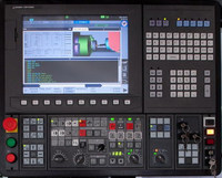
Okuma Alarm-B 2477 Sub-spindle mode
By a sub spindle machine, spindle mode was changed in C axis connection control.
Concerning new LT control, R Main spindle side was selection on the side of B Turret.
Object
SYSTEM
Code
1->With pickoff spindle, the G code other than G140 is designated for the G13 (A-turret) side in the G142 mode.
2->The spindle mode is switched in the C-axis control mode.
3->The spindle mode is switched in the flat turning mode.
4->G141 command is designated on B turret of the machine with sub-spindle.
5->In the LT model, sequence restart of the spindle is designated in the other spindle operation mode.
6->In the LT model, when there was saddle of one side on M02 instruction receipt conditions, another saddle performed spindle mode changing. Or,when there was saddle of one side on a synchronism standby condition of spindle mode changing instruction, another saddle accepted M02 instructions.
7->By LT machine, a saddle of one side under M100 command receipt condition was changed by another saddle.
Or, a saddle of one side received M100 command under a synchronous waiting condition of spindle mode change
command.
8->By the machine with Y-axis,G141 command was designated in Y axis mode.
11->The exchange instruction of the main spindle mode was executed on X-axis mirror image coordinate system.
13->When tool retraction interruption mode, G140/G141 command was ordered.
14->Concerning Sub spindle-tailstock Control specification, G141 command was designated at ‘tailstock mode’.
Probable Faulty Locations
NC part program
Program Example:
1)G13
G142
M84 ->An alarm occurs.
G140
2)G13
G140
G110
G141 ->An alarm occurs.
4)G14
G141(G140) -> An alarm occurs.
M110
Measures to Take
Check the program

