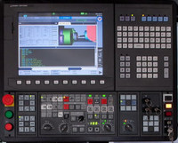
Okuma Alarm-P 0812 MCS initialization error
An error occurred in initialization of MCS when the power was supplied.
Index
None or axis name
Character-string
Varies with the code.
Code
XXXXYYYY
XXXX: Kind of generated alarm
YYYY: Further information on the alarm (Varies with XXXX.)
XXXX
FFFF…YYYY is 00UV. Where, U: Faulty channel number – 1
1= Channel 2
2= Channel 3
V: Cause of alarm (V=1 indicates that servo link mode has not been established.)
FF01…Memory error occurred in read/write test of the servolink I/O buffer.
Character-string shows the address where the error occurred.
FF00…Communication LSI caused an error in read/write test of the servo link I/O buffer.
Character-string shows the address where the error occurred.
F000…
bit 5:Missing ID number
bit 4:Too many CH4 controllers
bit 3:Too many CH3 controllers
bit 2:Too many CH2 controllers
bit 1:Too many CH1 controllers
bit 0:
With this error, connection data appears in the screen center.
EF00…The servo link does not connect with all the required axes or connects with an improper axis.
Character-string shows the problem axis name.
With this alarm, connection data appears in the screen center.
EE00…An error occurred in downloading an optional file.
YYYY shows the cause while low-order part is an error code.
If high-order digit=
2: File attribute is not contiguous.
3: File opening error. Low-order part is an error code.
4: Error in initial data reading. Low-order part is an error code.
5: File does not start with “MCS1”.
6: File name is not followed by “OPFS”.
7: The number of file sets is 0.
8: Data reading error. Low-order part is an error code.
9: File data has a sector length of 0.
A: The number of bytes transferred is 0.
B: File data has a sector length smaller than the number of bytes transferred.
C: Data reading error. Low-order part is an error code.
ED00…An error occurred when manual mode is switched to auto mode. High-order digit of
EC01…Time difference occurred in setting CH1 timer.
EC02…Time difference occurred in setting CH2 timer.
EC03…Time difference occurred in setting CH3 timer.
D001…In buffering the initial data in AT (auto) receive mode, the software synchronization bit does not come on within 3 seconds.
D002…In buffering the initial data in AT (auto) receive mode, the buffer A received a wrong format code.
Two low-order characters of
D003…In buffering the initial data in AT (auto) receive mode, the buffer B received a wrong format code in the first block.
D004…In buffering the initial data in AT (auto) receive mode, the buffer B received a wrong format code in the second block.
D005…In buffering the initial data in AT (auto) receive mode, the buffer B received a wrong format code in the third block.
D006…In buffering the initial data in AT (auto) receive mode, the buffer B received a wrong format code in the fourth block.
D007…In buffering the initial data in AT (auto) receive mode, the buffer B received a wrong format code in the fifth block.
D008…In buffering the initial data in AT (auto) receive mode, the buffer B received a wrong format code in the sixth block.
D009…In buffering the initial data in AT (auto) receive mode, the buffer B received a wrong format code in the seventh block.
D00A…In buffering the initial data in AT (auto) receive mode, the buffer B received a wrong format code in the eighth block.
D010…In buffering the initial data in AT (auto) receive mode, the received self-diagnostic data is not $55.
D011…In buffering the initial data in AT (auto) receive mode, the buffer A received the bit data which is wrong at bit No. 0 and No. 1.
D012…In buffering the initial data in AT (auto) receive mode, the buffer A received the bit data which is wrong at bit No. 2 and No. 3.
D013…In buffering the initial data in AT (auto) receive mode, the buffer A received the bit data which is wrong at bit No. 4 and No. 5.
D080…Initial data buffered in AT (auto) receive mode includes wrong data at ID data No. 441C.
D081…Initial data buffered in AT (auto) receive mode includes wrong data at ID data No. 2428.
D090…Initial data buffered in AT (auto) receive mode includes wrong data at ID data No. 4405.
D091…Initial data buffered in AT (auto) receive mode includes wrong data at ID data No. 4404.
D092…Initial data buffered in AT (auto) receive mode includes wrong offset data for compensating positioning points.
Probable Faulty Locations
– Inverter unit (Check the LED of the inverter unit.)
– Improper ID number set in MCS
– Specification code setting error
– Erroneous connection with MCS

