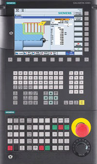
Sinumerik Alarm 14710 Channel %1 block %2 error in initialization sequence in function %3
Parameters:
%1 = Channel number
%2 = Block number, label
%3 = Identifier of the function which caused the error
Definitions:
Initialization blocks are generated (or not) after control power-up, program reset and program start, depending on the settings in machine data $MC_RESET_MODE_MASK and $MC_START_MODE_MASK.
Errors can occur because of incorrect machine data settings. The errors are output with the same error messages as appear if the function was incorrectly programmed in the part program.
This alarm is generated in addition, in order to indicate that an error refers to the initialization sequence.
Parameter %3 specifies which function triggers the alarm: Control power-up and (program) RESET: Value:
0: Error during synchronization preprocessing/main run
1: Error on selection of tool length compensation
2: Error on selection of transformation
3: Error on selection of zero offset
The macro definitions and cycle interfaces are also read in during the power-up proce- dure. If an error occurs here, this is indicated by value = 4, or value = 5 (Program) START: Value
100: Error during synchronization preprocessing/main run
101: Error on selection of tool length compensation
102: Error on selection of transformation
103: Error on selection of synchronized spindle
104: Error on selection of zero offset Particularly when tool management is active, it is possible that a tool on the spindle or the tool holder is disabled but still needs to be activated. These tools are automatically activated on RESET. On START, machine data $MC_TOOL_CHANGE_ERROR_MODE can be used to specify whether an alarm is generated or an automatic bypass strategy is applied.
If the parameter contains 3 values from 200 to 203, this means that an insufficient number of NC blocks is available for NC block preparation on certain commands (ASUP start, overstore selection, teach-in).
Remedy:
Increase machine data $MC_MM_NUM_BLOCKS_IN_PREP.
Reactions:
– Interpreter stop
– Channel not ready.
– NC Start disable in this channel.
– Interface signals are set.
– Alarm display.
Remedy:
Please inform the authorized personnel/service department.On parameter %3= 0 -3:
If the alarm or alarms occur on RESET:Check the settings of machine data $MC_RESET_MODE_MASK,
$MC_TOOL_RESET_VALUE, $MC_TOOL_PRESEL_RESET_VALUE,
$MC_TOOL_RESET_NAME (only if tool management is active),
$MC_CUTTING_EDGE_RESET_VALUE, $MC_SUMCORR_RESET_VALUE,
$MC_TOOL_CARRIER_RESET_VALUE,
$MC_GCODE_RESET_VALUES, $MC_EXTERN_GCODE_RESET_VALUES,
$MC_TRAFO_RESET_VALUE,
$MC_COUPLE_RESET_MODE_1,
$MC_CHBFRAME_RESET_MASK
On parameter %3= 100 – 104:Check the setting of machine data $MC_START_MODE_MASK and the machine data specified under ‘…_RESET_…’. Check machine data. If tool management is active, remove the specified tool from the toolholder/spindle and, if necessary, cancel the ‘disabled’ status.
On parameter %3= 4 or 5:Check macro definitions in _N_DEF_DIR Check cycle directories _N_CST_DIR and _N_CUS_DIR
On parameter %3= 200 to 203:Increase machine data $MC_MM_NUM_BLOCKS_IN_PREP.
Program Continuation:
Clear alarm with the RESET key. Restart part program
References
- Siemens Diagnostics Guide by Siemens

