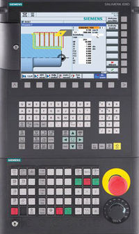
Sinumerik Alarm 20006 Channel %1 axis %2 reference point creep velocity not reached
Parameters:
%1 = Channel number
%2 = Axis name, spindle number
Definitions:
In phase 2 of reference point approach (wait for zero mark), the cam end was reached but the reference point approach velocity was not within the tolerance window. (This can occur when the axis is already at the end of the cam at the beginning of reference point approach. This means that phase 1 has already been concluded and will not be started.) Phase 2 has been interrupted (this time before the cam) and the reference point traversing will be started once again automatically with phase 1. If the approach velocity is not attained at the second attempt either, the referencing will be aborted with the alarm display. Approach velocity: 34040 REFP_VELO_SEARCH_MARKER Velocity tolerance: 35150 SPIND_DES_VELO_TOL.
Reactions:
– NC Stop on alarm.
– NC Start disable in this channel.
– Alarm display.
– Interface signals are set.
– If the axis is a single axis when this alarm is triggered, the alarm is only effective for this axis (not effective for e.g. the channel or mode group)
Remedy:
Please inform the authorized personnel/service department. Reduce the MD for the approach velocity 34040 REFP_VELO_SEARCH_MARKER and/or increase the MD for the velocity tolerance 35150 SPIND_DES_VELO_TOL.
Program Continuation:
Clear alarm with the RESET key. Restart part program
References
- Siemens Diagnostics Guide by Siemens

