Contents
Osai GTL (HIGH LEVEL GEOMETRIC PROGRAMMING)
Osai 10 Series CNC systems permit to program a geometric profile on the plane using either the standard programming language (G1-G2-G3) or GTL, a high level programming language.
Osai GTL makes it possible to use the information provided by the drawing in order to program a profile made up of straight lines and circles. The Osai 10 Series CNC calculates tangency and intersection points between these elements.
Osai GTL and standard programming codes can be used in the same program but not in the same profile.
GTL requires absolute programming mode (G90).
Geometric Elements
Osai GTL uses lower case letters
- a – angles
- l – straight lines
- c – circles
- d – distances
- m – modules
- o – reference origins
- r – radiuses
- p – points
- s – intersection numbers
- b – bevels
Programming
NAME INDEX = <Expression>
where
NAME is one of the symbols for geometric element e.g.:
o defines reference origins
p defines points
I defines straight lines
c defines circles
INDEX defines the number of the NAME geometric variable (element).
It is a number ranging from 0 to the maximum configured limit.
expression provides all the information that defines the geometric element.
Examples
Examples of element definitions:
o1 = X30 Y30 a45
p1 = o1 X15 Y15
p2 = X60 Y30
l1 = p1, p2
l2 = X30 Y50, a45
c1 = l1,l2,r15
l3 = X0 Y0, X100 Y60
p3 = l3, c1
c2 = p3,r8
Definition of Points
Example1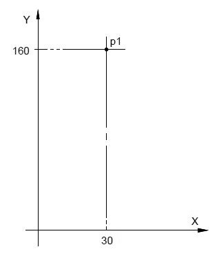
p1 = X30 Y160
Example2
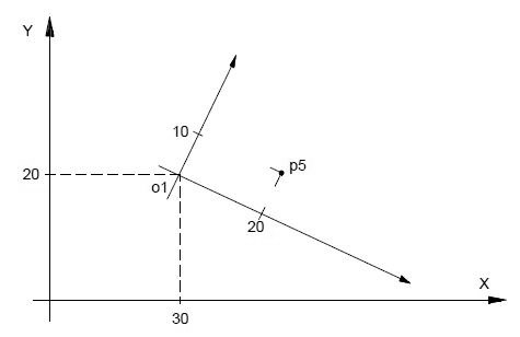
o1 = X30 Y20 a-20
p5 = o1 X20 Y10
Definition of Straight Lines
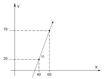
l1 = X40 Y20, X60 Y70
Definition of Circles
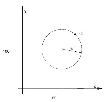
c2=I50J100r-40

